This section provides general requirements3 related to implementing all grid support DER utility interactions. The related IEEE 2030.5 specific requirements can be found in Section 5.
4.1 Security Requirements
IEEE 2030.5 security requirements are covered in section 5.2.1. Although outside the scope of CSIP, security SHOULD be used in all non-IEEE 2030.5 interactions between the Aggregators, site hosts, GFEMS, and DERs and other entities receiving or transmitting DER related communications. Security includes data in motion (e.g. encryption of communications), data at rest, the authentication of clients
![]()
2 The full set of requirements can be found in appendix B
3 The key words "SHALL", “SHOULD”, “MUST” and “MAY” in this document when capitalized constitute normative text and are to be interpreted as described in [RFC 2119].
and services, as well as the authorization of all requests. The composition of any Aggregator or DER access to utility servers is managed via contractual relationships. As such, the specific permissible actions across different utility servers may be different. See utility handbooks or programs/contracts for further cyber security requirements.
4.2 Registration and Identification of DERs
The registration of DER Clients is utility specific and is assumed to be outside the scope of CSIP. The registration process may result in the delivery of a globally unique identifier (GUID) associated with a particular DER. The GUID provides a shared name between the utility and the other party to ensure that operations and data are routed appropriately. The GUID is used to guarantee its authenticity and uniqueness within the scope of a single utility’s CSIP server. For DER Clients that have an IEEE 2030.5 certificate, the GUID SHALL be derived from this certificate (see section 5.2.1.2). Implementers SHALL refer to each utility’s Interconnection Handbook for requirements related to the creation, use or management of this identifier.
4.3 Group Management
Effective utility management of DERs requires that their location from an electrical system perspective be known. As a result, a special management function is required to align DERs operated by Aggregators to the utility system topology or other utility defined grouping. In certain cases, settings or commands can be sent to the entire system under a specific Aggregator’s control. In other cases, the settings or commands will be targeted to limited numbers of DERs due to differences in needs across the utilities distribution system. For the purposes of this specification, DERs can be assigned to a minimum of one group and a maximum of 15 groups.
Although topological grouping is expected to be the primary use case, any type of grouping is allowed. A group consisting of DERs from a specific vendor or a group of DERs enrolled on a special program can be implemented. Each utility will apply the grouping levels as it sees fit to meet its own operational needs. For example, distribution transformer-level grouping is likely to be a future rather than a near term requirement. Likewise, other utilities may want to apply these group constructs in support of other distribution system network models.
Group membership may change over the life of the inverter being interconnected to the utility’s system.
These changes can be the result of system configuration or changes in segmentation or equipment. Aggregators and DER Clients SHALL support IEEE 2030.5 based grouping and full lifecycle management of group relationships as defined within Section 5.2.3 and within each utility’s Interconnection Handbook or program/contract requirements.
Finally, a key concept of grouping is that DER can exist in multiple groups to support utility management at differing levels of the system. In all cases, the utility is responsible for maintaining these groups over time and to deliver any changes to groups to the impacted DERs.
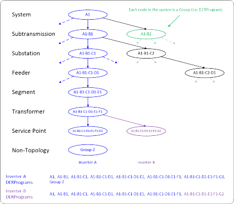
Figure 3 - Sample Grouping with Topology and Non-Topology Groups
1. System – refers to the utility service territory in total. All inverters are assigned to this group. It is expected that an inverter’s membership will never change.
2. Sub-transmission – refers to a section of a utility’s service territory where the transmission grid is managed directly by the utility
3. Substation – refers to the substation from which the inverter is electrically connected. Note that this group assignment can change as the electric system topology changes.
4. Feeder– refers to the feeder that the inverter is attached to. Note that this group assignment can change as the electric system topology changes.
5. Segment – refers to a section of a distribution feeder/circuit that cannot be further isolated or modified via switching or other sectionalizing device.
6. Service Transformer – refers to the collection of service points that are electrically connected to a single service transformer.
7. Service Point – refers to the point of common coupling between the utility and a 3rd party facility where one or more smart inverters are present.
8. Non-Topology- refers to a DER that has been placed in a group based on utility system needs
4.4 DER Control Events and Settings
4.4.1 Definition and Usage
Before listing the requirements, some terms that are used in this guide need to be defined and explained.
• A DER control is a generic term for a grid control function (e.g. fixed power factor or connect/disconnect).
• A DERControl is an IEEE 2030.5 control event that contains a start time, a duration, and a control parameter value. An example of a DERControl resource is the fixed power factor control event DERControl:opModFixedPF.
• A DefaultDERControl is an IEEE 2030.5 control resource that is in effect if there are no active DERControls for that resource. For example, the DefaultDERControl:opModFixedPF resource is in effect when there are no DERControl:opModFixedPF events active.
For most DER controls, there are two ways to issue the control: using DERControl events or using
DefaultDERControls.
When the start time and duration of the control is known, the typical way to issue the control is to create a DERControl event for the control. Like any IEEE 2030.5 event, DERControl events can be scheduled, superseded, cancelled, etc. If configured, the utility DER server can receive the event status responses (e.g. received, started, completed, superseded, etc.) of the DERControl from each DER.
When the DER control is intended to be used to modify a setting (i.e. start time is “now” and the duration is indefinite), the most natural way to issue the control is to create or update the DefaultDERControl. The DefaultDERControl will be in effect until it is changed or a DERControl event occurs. In many use cases, the utility server may simply use DefaultDERControls and never issue a DERControl event for the controls. One limitation of using DefaultDERControls is there are no status responses associated with DefaultDERControls.
If status responses for modification of settings are needed, the utility server can use DERControl events. To accomplish this, the start time of the DERControl is “now”, and the duration is set to a very large, effectively infinite, number. To change the DERControl setting, a new DERControl is issued to supersede or cancel the existing DERControl.
4.4.2 Requirements
All DERs and related communications will support the Autonomous and Advanced functionality and controls as shown below.
Grid Support DER Functions | |
Autonomous Functions | Advanced Function |
Anti-Islanding | Connect/Disconnect |
Low/High Voltage Ride Through | Limit Maximum Active Power Mode |
Low/High Frequency Ride Through | Scheduling Power Values and Modes |
Ramp Rate Setting | Monitor Key Data including Alarms, DER Status and Output |
Dynamic Volt-Var | Volt-Watt Control |
Fixed Power Factor Control | Frequency-Watt Control |
Set Active Power Mode |
Table 1 – Grid DER Functions
Default settings or modes for Autonomous Functions, including which are activated and deactivated at deployment, will be specified in the applicable interconnection tariff and/or the utility’s Interconnection Handbook. Autonomous functions’ default settings SHALL be changeable via IEEE 2030.5 DefaultDERControl communications. Modifications to default settings SHALL occur immediately upon receipt and have an indefinite duration.
Scheduling Autonomous and Advanced Power Values and Modes SHALL be controllable via IEEE 2030.5 DERControl events. As opposed to modification of default settings, these events allow the server to schedule operations for single or groups of DERs at a future point in time for a specific duration.
Through events, the utility can send one or more operations as a sequence to the DERs for processing and implementation. In this way, the utility can schedule and sequence DER control events.
Aggregators and DER Clients SHALL be responsible for assuring that all operations received from the utility are processed in the appropriate time sequence as specified by the utility.
An Aggregator acting for its DERs and DER Clients SHALL be able to store at least 24 scheduled DER control events for each DER.
In the absence of scheduled controls, DERs SHALL revert to a default control setting specified by interconnection tariffs, the utility Interconnection Handbook or as specified by the last DefaultDERControl.
Should there be a loss of communications, DERs SHALL complete any scheduled event and then revert to default settings or other settings as determined by the site host or tariffs/contracts.
4.4.3 Prioritization
When commanded in a manner where two or more operations are in conflict, the interpreting system SHALL operate against the control operation which has the highest priority subject to the systems capability, contracts and self-protection requirements.
In setting up commands for groups of DERs, it is expected that commands for lower level groups will typically have precedence over higher level groups (i.e. commands at the System level are trumped by commands at a more local level Feeder). In this manner, multiple needs can be managed. For example, a system level group operation might call for a voltage-watt mode of operation with a set of curve parameters at the same time as several circuits might require a voltage-watt mode with a different set of curve parameters.
The utility will avoid creating situations where there can be conflicting commands of the same priority. If avoidance of conflicting commands is not possible, the more recently received command SHOULD have precedence over the older command. In either case, it SHALL be the responsibility of the Aggregator or DER Client to decide how to handle two simultaneous controls.
4.5 Communication Interactions
For Aggregator communications, notifications and call backs (subscription/notification) SHALL be used to limit system polling to the greatest extent practical.
To simplify communication requirements for Direct DER Communications scenarios, unless specified otherwise in utility Interconnection Handbooks or programs/contracts, all communications SHALL be initiated by the DER Client (i.e., client-side initiation). This model of communication eliminates the need for unsophisticated parties to make changes in networking security based on the needs of CSIP. In Direct DER communication scenarios, the client system SHALL initiate communications with the utility according to pre-defined polling and posting intervals to ensure the DER has up to date settings and the utility understands the operational state of the DER. Unless specified in each utility’s Interconnection Handbook or programs/contracts, default polling and posting rates SHALL be as follows:
• Polling of DERControls and DefaultDERControls (Direct DER Communication)– every 10 minutes
• Posting monitoring information (Direct and Aggregator Mediated Communications)– every 5 minutes
For DERs with an external SMCU, the SMCU SHALL transfer the DER control to the DER within 10 minutes of receiving the control from the server.
For DERs with a GFEMS, the GFEMS SHALL transfer the DER control to the DERs within 10 minutes of receiving the control from the server.
For DERs mediated by Aggregators, the Aggregator SHALL transfer the DER control to the DERs within 15 minutes of receiving the control from the server.
4.6 Reporting DER Data
4.6.1 Monitor Data
Aggregators acting for its DERs and DER Clients SHALL have the capability to report the monitoring data in Table 2. Aggregators acting for its DERs and DER Clients SHALL have the capability to include the data qualifiers in Table 3. All measurement SHALL include a date-time stamp. Unless otherwise specified in each utility’s Interconnection Handbook or programs/contracts, Aggregators acting for its DERs and DER Clients SHALL report the monitoring data in Table 2 and MAY include the data qualifiers in Table 3.
Monitoring Data |
Real (Active) Power |
Reactive Power |
Frequency |
Voltage per Phase |
Table 2 - Monitoring Data
Data Qualifiers |
Instantaneous (Latest) |
Maximum over the Interval |
Average over the Interval (the last posting) |
Minimum over the Interval |
Table 3 - Data Qualifiers
Note that some DERs may be capable of only reporting instantaneous measurements and cannot report minimum, maximum, or average values. For those situations where the DERs cannot provide Monitoring Data, the Aggregator acting for its DERs and DER Clients SHALL not send the data.
4.6.2 Status Information
4.6.2.1 Ratings and Settings
Aggregators acting for its DERs and DER Clients SHALL have the capability to report the Nameplate Ratings and Adjusted Settings information shown in Table 4. Nameplate Ratings and Adjusted Settings SHOULD be reported once at start-up and whenever there is a change in value. This information is not expected to change during normal operation. The Nameplate Rating is the value of the item as manufactured. The Adjusted Setting is the modified value of the Nameplate Rating to account site- specific deviations, degradations over time, or other factors. Specific requirements related to when Nameplate Ratings and Adjusted Setting must be provided will be found in each utility’s Interconnection Handbook or contracts/programs.
Nameplate Ratings and Adjusted Settings |
Maximum rate of energy transfer received |
Maximum rate of energy transfer delivered |
Maximum apparent power |
Maximum reactive power delivered |
Maximum reactive power received |
Maximum active power |
Minimum power factor displacement |
Table 4 - Nameplate Ratings and Adjusted Settings
4.6.2.2 Operational Status Information
Aggregators acting for its DERs and DER Clients SHALL have the capability to report the dynamic Operational Status Information shown in Table 5. The frequency of reporting will be specified in each utility’s Interconnection Handbook or contracts/programs.
Operational Status Information |
Operational State |
Connection Status |
Alarm Status |
Operational Energy Storage Capacity |
Table 5 – Operational Status Information
4.6.3 Alarms
Aggregators acting for its DERs and DER Clients SHALL have the capability to report the alarm data shown in Table 6 as they occur. For each alarm, there is a corresponding “return to normal” message. All alarms and their “return to normal” messages SHALL include a date-time stamp along with the alarm type. The frequency of reporting of alarms will be specified in each utility’s Interconnection Handbook or contracts/programs.
Alarms |
Over Current |
Over Voltage |
Under Voltage |
Over Frequency |
Under Frequency |
Voltage Imbalance |
Current Imbalance |
Local Emergency |
Remote Emergency |
Low Input Power |
Phase Rotation |
Table 6 – Alarms
By design, low-level equipment health and status information is not part of this interface as the utility does not have maintenance responsibility for these 3rd party operated systems.