5 IEEE 2030.5 Implementation and Requirements
This section defines IEEE 2030.5 implementation requirements and maps them to the CSIP and necessary Grid DER Support capabilities. The specific version of the protocol implemented SHALL be IEEE 2030.5-2018.
While it is assumed that the reader has a working knowledge of IEEE 2030.5 concepts and operations, a brief overview of IEEE 2030.5 is provided below to help the reader understand the detailed requirements.
5.1 Overview
5.1.1 High-Level Architecture
The IEEE 2030.5 protocol implements a client/server model based on a representational state transfer (REST) architecture utilizing the core HTTP methods of GET, HEAD, PUT, POST, and DELETE. In the REST model, the server hosts resources, and the client uses the HTTP methods to act on those resources. In this guide, the server is implemented at the utility communications gateway, and the client is then implemented at the Aggregator system or the SMCU or GFEMs (aka DER Clients). The client typically initiates the action, but the protocol does provide a lightweight subscription mechanism for the server to push resources to the client.
5.1.2 Resources and Function Sets
Function Set | Utility Server | Aggregator | DER Client |
Time | MUST | MUST | MUST |
Device Capability | MUST | MUST | MUST |
End Device | MUST | MUST | MUST |
FSA | MUST | MUST | MUST |
DER | MUST | MUST | MUST |
Response | MAY | MUST | MUST |
Meter/Mirror Meter | MAY | MUST | MUST |
Log Event | MUST | MUST | MUST |
Subscription/Notification | MUST | MUST | MAY |
Security | MUST | MUST | MUST |
Table 7 - Required Function Sets and Resources
5.1.2.1 Time
The utility server uses the Time function set to distribute the current time to clients. Time is expressed in Coordinated Universal Time (UTC). Server event timing is based on this time resource. Unless
otherwise specified in the utility’s Implementation Handbook, coordination of this time and rates for updating this time SHALL conform to the requirements of IEEE 2030.5-2018.
5.1.2.2 Device Capability
The utility server uses the DeviceCapability resource to enumerate the function sets it supports. Clients use this function set to discover the location (URL) of the enumerated function sets.
5.1.2.3 End Device
The EndDevice function set provides interfaces to exchange information related to specific client or EndDevice. In the Direct DER Communications scenario, the SMCU and the GFEMS are EndDevices. In the Aggregator scenario, the Aggregator itself and all the DERs it manages are all EndDevices. The EndDevice resource can contain the EndDevice:DER resource. This resource contains links for DERs to report their status.
Aggregators acting for its DERs and DER Clients SHALL support the EndDevice:DER resources in Table 8 if the utility server makes them available.
EndDevice:DER Resource |
DERCapability |
DERSettings |
DERStatus |
DERAvailability |
Table 8 - Required EndDevice:DER Resources
5.1.2.4 Function Set Assignments (FSA)
The FunctionSetAssignments function set provides the mechanism to convey the grouping assignments of each DER. Grouping with FSAs can be implemented in many ways. Section 5.2.3.1 explains the required method for CSIP.
5.1.2.5 Distributed Energy Resource (DER)
The DER function set provides an interface to manage Distributed Energy Resources (DER). It is the primary function set for issuing DER controls.
5.1.2.5.1 DERProgram
The top-level resource for organizing DER controls is the DERProgram. In CSIP, the DERProgram is the resource used to convey controls to a group (i.e. each controllable group has an associated DERProgram for issuing controls to that group). The DERProgram contains an mRID to identify the resource, a primacy value to specify the priority of the DERProgram relative to other DERPrograms, and links to the DefaultDERControl, DERControlList, and the DERCurveList.
5.1.2.5.2 DefaultDERControl
Each DERProgram can have a DefaultDERControl that specifies the control values that are in effect in the absence of an active DERControl. DefaultDERControls can be used as “settings” for controls that are expected to be in effect for long durations without a definite end time (see section 4.4.1). The server can from time to time modify the DefaultDERControls. As with DERContols, clients periodically monitor the DefaultDERControls for changes (See Section 4.5).
5.1.2.5.3 DERControl
DERControls are events that specify the control value(s) to be used at a specific time for a specific duration. For example, a DERControl can specify a fixed power factor value be used at a certain time for a certain duration. When a DERControl is active, it overrides any existing DefaultDERControl for that specific control. DERControls are typically when the start time and stop time are known, but they can also be used when the end time is unknown. In this case, the DERControl is created with a very long duration and is cancelled or superseded when the control is no longer in effect.
5.1.2.5.4 DERCurve
DERCurves are a type of DERControl that define behavior based on an X-Y curve instead of a fixed value. DERCurves are used to define the behavior of a DER in response to a sensed grid condition. These curves are already embedded in the DER. The curve management functionality is used to update the set points on a specific curve and determine which curves are active at a point in time. While only one curve per curve-type can be active at the same time, different curve-types can be active at the same time if they do not conflict.
These curves are used to provide autonomous control in a predictable fashion. For example, assuming a volt-watt curve is active; if the inverter senses an over voltage situation a volt-watt curve would direct the inverter to lower its power output. Likewise, in an under-voltage situation, the same curve would likely direct the DER to increase its output (if possible).
5.1.2.6 Response
The Response function set provides the resources needed for the Aggregator or DER Client to report the status of DERControl events. Typical response information includes event reception, event start, event completion, event cancellation, etc.
5.1.2.7 Metering and Metering Mirror
The Metering function set provides the resources needed to support metrology measurements (e.g. real power, reactive power, voltage, etc.) The Metering Mirror function set provides the resources needed for an Aggregator or DER to send metrology data to the utility server.
5.1.2.8 Log Event
The LogEvent function set provides the resources needed for the Aggregator or DER to send alarms to the utility server.
5.1.2.9 Subscription/Notification
In the Aggregator scenario, the utility server provides resources to support subscriptions that allow rapid notification of a change in the resource. For example, the utility might change a Volt-VAr curve to reflect new tolerances based on the level of solar penetration on a feeder. The Aggregator implements a notification resource to receive the notifications sent by the utility server.
5.2 IEEE 2030.5 Requirements
Aggregators and DER Clients SHALL meet all IEEE 2030.5 mandatory requirements that are described in the standard for each of these sections/functions unless otherwise specified in utility Interconnection Handbooks or programs/contracts.
5.2.1 Security Requirements
HTTPS SHALL be used in all Direct and Aggregator Mediated communications scenarios.
IEEE 2030.5 defines a specific security framework (i.e. PKI infrastructure). However, this framework may not be compatible with the utility’s security and IT infrastructure requirements. Therefore, the utility has the option of mandating the implementation and use of other security frameworks as defined in this section or in utility Interconnection Handbooks or programs/contracts (e.g., Site to Site VPNs, Cipher Suites, Certificates, etc.).
Aggregators and DER Clients SHALL support the required IEEE 2030.5 security framework and other security frameworks as required by the utility Interconnection Handbook or programs/contracts.
In all cases, including Aggregator Mediated communications scenarios and Direct Communication scenarios, the utility should specify the security framework based on its security and IT requirements. Possible PKI options include:
• Use of the IEEE 2030.5 or CSIP defined Certificate Authority (CA)
• Contracting with a commercial, third-party certificate authority chain to generate certificates
• Implementing their own private certificate authority chain to generate certificates
• Using self-signed certificates
5.2.1.1 TLS and Cipher Suites
TLS version 1.2 SHALL be used for all HTTPS transactions.
IEEE 2030.5 specifies a single cipher suite for HTTPS communications, namely: TLS_ECDHE_ECDSA_WITH
_AES_128_CCM_8 using the elliptic curve secp256r1. DER Clients SHALL support the IEEE 2030.5 cipher suite.
Aggregators SHALL also support the TLS_RSA_WITH_AES_256_CBC_SHA256 cipher suite or other cipher suites as specified by the utility Interconnection Handbook or programs/contracts.
5.2.1.2 Certificates
Certificates provide a mechanism to authenticate identities during the TLS handshake. All utility servers, Aggregators, and DER Clients SHALL have a valid certificate. A valid certificate is a certificate that
conforms to the IEEE 2030.5 security framework or the security framework specified by the utility Interconnection Handbook or programs/contracts. A valid certificate SHALL be used in all IEEE 2030.5 TLS transactions.
Certificates for Aggregators and DER Clients SHALL only be provisioned upon completion of Conformance Testing.
Conformance testing and certificate provisioning and usage requirements will be specified in interconnections tariffs or utility Interconnection Handbooks or programs/contracts.
The GUID for both Aggregators and DERs SHALL be the IEEE 2030.5 Long Form Device Identifier (LFDI) which is based on the 20-byte SHA-256 hash of the device’s certificate.
5.2.1.3 Authentication
The utility server, Aggregator, and DER Clients perform mutual authentication during the TLS handshake by exchanging and authenticating each other’s certificate. The certificates specified by each utility SHALL be used for authentication. Authentication consists of verifying the integrity of the received certificate, checking the certificate has not expired, and verifying the certificate chains back to the correct root certificate authority. If authentication fails, the authenticator SHOULD issue a TLS Alert – Bad Certificate and close the connection.
5.2.1.4 Authorization
The utility server maintains a list of authorized devices (i.e. Aggregators and DERs) that are permitted to communicate with the server. For Aggregators and DER Clients, the authorization list SHALL be based on the LFDI since the SFDI may not provide enough collision protection for a large population (e.g. 1 million) of devices. If the device is not on the authorization list, the utility server SHOULD return an HTTP error code (e.g. 404 – Not Found) to terminate the transaction.
5.2.1.5 Access Control
Once a device (i.e. Aggregators or DER Clients) has been authenticated and authorized, it potentially has access to resources on the utility server. The utility server controls access to resources based on Access Control Lists (ACL). In theory, every resource on the utility server can have its own ACL. The utility SHALL establish the permissions for read, write, control, and other interactions, based on agreements on which interactions are authorized between each DER and the utility. For example, role-based access control may be used to establish these permissions for different roles.
Another aspect of Access Control is that the utility server may present different resource information based on the identity of the device making the request. This is done for both efficiency and/or privacy reasons.
When an Aggregator accesses the EndDeviceList, the utility server SHALL only present EndDevices that are under the management of that Aggregator. This means the utility server will present each Aggregator with a different EndDeviceList. This is done for both efficiency (Aggregators know that all DERs in the list are under its control), and privacy (Aggregators do not see any information related to DERs not under its control).
5.2.2 Commissioning and Identification of DER Requirements
IEEE 2030.5 uses two identifiers, both of which are hashes of the device certificate. The Short-Form Device Identifier (SFDI) is based on a 36-bit SHA256 hash of the device certificate and is expressed as 12 decimal digits. The Long-Form Device Identifier (LFDI) is the first 20 bytes of the SHA256 hash of the device certificate. In the Direct DER Communications scenario, the GUID used to identify the DER SHALL be the DER’s LFDI.
In the Aggregator scenario, the DERs under the management of the Aggregator may not be IEEE 2030.5 devices – that is, they may not have a device certificate. In this case, the utility or the Aggregator will produce the LFDI (see section 5.2.1.2). In all cases, this identity and the associated LFDI are returned to the Aggregator for their uses in ensuring communications are routed correctly. Implementers SHOULD
refer to each utility’s Interconnection Handbook or programs/contracts for more information needed to establish the LFDI.
In the rare event that an LFDI collision is detected (i.e. two unique certificates or IDs hash to the same LFDI value), the utility will replace the certificates or IDs of the offending DERs. This may require returning the DERs to the manufacturer for certificate replacement. Note that the probability of a LFDI collision is infinitesimally small. It is much more likely the collision was caused by an accidental duplication of the certificate or ID.
5.2.3 Group Management Requirements
The primary function of groups is the ability to target DER controls to members of those groups. In IEEE 2030.5, DER controls exist within DERPrograms, so effectively, each controllable group has one associated DERProgram to receive the group’s DER controls. Aggregators acting for its DERs and DER Clients SHALL track the DERProgram associated with that group. CSIP allows DERs to be a member of up to 15 groups. Aggregators acting for its DERs and DER Clients SHALL support up to 15 DERPrograms simultaneously for each DER.
Figure 3 shows an example grouping structure containing both topological and non-topological groups and the associated DERPrograms being tracked by two DERs.
Note that the utility server does not need to associate a DERProgram for each group. It only needs to associate a DERProgram to those groups it intends to send controls to. For example, if the utility does not intend to send controls at the Substation level, it does not need to create a DERProgram for the Substation groups. To minimize resource requirements for the utility server, Aggregators, and DERs, the utility server SHOULD only create DERPrograms for groups that are intended to receive controls.
5.2.3.1 FSA Architecture
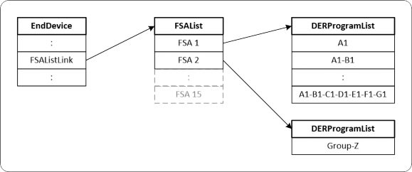
In IEEE 2030.5, group membership is conveyed to an Aggregator or Directly Communicated to a DER using the FunctionSetAssignmentsListLink in the DER’s EndDevice instance. This link points to a FunctionSetAssignmentsList (FSAList) that is usually unique to each DER. This list contains one or more FunctionSetAssignments (FSA). Each FSA can contain a link to a DERProgramList which contain link to a DERProgram the DER is required to track. Aggregators acting for its DERs and DER Clients SHALL traverse all these links and lists to discover all DERPrograms the DER is required to track.
The utility server can structure the FSAs to achieve its grouping objectives in many ways. CSIP has chosen the model shown in Figure 4 to promote efficiency and interoperability.
Figure 4 - CSIP FSA Model
In the above model, the FSA 1 points to a DERProgramList that contains all DERPrograms for topology groups. FSA 2 points to a DERProgramList containing a DERProgram for a non-topology group.
For each DER EndDevice, the utility server SHALL use one FSA to point to a DERProgramList containing all topology-based DERPrograms and MAY use additional FSAs to point to a DERProgramList containing
non-topology-based DERPrograms. DER Clients SHALL be capable of supporting 15 FSAs.
For the CSIP Direct Communication scenario, the DER Client SHALL only receive function set assignments for a single energy connection point reflecting the aggregate capabilities of the plant at its point of common coupling with the utility.
5.2.4 DER Controls and DER Default Control Requirements
DER Clients SHALL use the IEEE 2030.5 mappings for the Grid DER Support Functions shown in Table 9.
Grid DER Support Functions | IEEE 2030.5 DERControls | IEEE 2030.5 DefaultDERControls |
Low/High Voltage Ride Through | opModLVRTMUSTTrip opModLVRTMAYTrip opModLVRTMomentaryCessation opModHVRTMUSTTrip opModHVRTMAYTrip opModHVRTMomentaryCessation | opModLVRTMUSTTrip opModLVRTMAYTrip opModLVRTMomentaryCessation opModHVRTMUSTTrip opModHVRTMAYTrip opModHVRTMomentaryCessation |
Low/High Frequency Ride Through | opModLFRTMUSTTrip opModLFRTMAYTrip opModHFRTMUSTTrip opModHFRTMAYTrip | opModLFRTMUSTTrip opModLFRTMAYTrip opModHFRTMUSTTrip opModHFRTMAYTrip |
Ramp Rate Setting | setGradW setSoftGradW | |
Connect/Disconnect | opModEnergize | opModEnergize |
Dynamic Volt-VAr | opModVoltVar | opModVoltVar |
Fixed Power Factor Control | opModFixedPF | opModFixedPF |
Real Power Output Limit Control | opModMaxLimW | opModMaxLimW |
Volt-Watt Control | opModVoltWatt | opModVoltWatt |
Frequency-Watt Control | opModFreqWatt | opModFreqWatt |
Set Active Power Mode (in percentage of Max power) (in Watts) | opModFixedW opModTargetW | opModFixedW opModTargetW |
Table 9 – Grid DER Support Functions to IEEE 2030.5 Control Mapping.
Usage of DERControls and DefaultDERControls was described in section 4.4.1. Note that the Ramp Rate Settings function maps to a DefaultDERControl and not a DERControl. This means they cannot be scheduled and can only be changed by changing the DefaultDERControl object.
5.2.4.1 Scheduling of Controls
DERControls are IEEE 2030.5 events and SHALL conform to all the event rules in Section 12.1.3 of IEEE 2030.5-2018.
Aggregators SHALL subscribe to each DERProgramList assigned to its DERs to discover changes in
DERProgram:primacy.
Aggregators SHALL subscribe to the DERControlList of each DERProgram assigned to its DERs to discover new controls or changes to existing controls.
Aggregators SHALL subscribe to the DefaultDERControl of each DERProgram assigned to its DERs to discover changes to the default controls.
Unless otherwise specified in utility Interconnection Handbooks or programs/contracts to allow subscriptions, DER Clients SHALL poll to each DERProgram assigned to it to discover changes in DERProgram:primacy.
Unless otherwise specified in utility Interconnection Handbooks or programs/contracts to allow subscriptions, DER Clients SHALL poll to the DERControlList of each DERProgram assigned to it to discover new controls or changes to existing controls.
Unless otherwise specified in utility Interconnection Handbooks or programs/contracts to allow subscriptions, DER Clients SHALL poll to the DefaultDERControl of each DERProgram assigned to it to discover changes to the default controls.
The utility MAY optionally specify a recommended polling rate for these resources using the
DERProgramList:pollRate resource. If the polling rate is specified, DERs SHOULD poll at this rate.
5.2.4.2 Prioritization
Prioritization of events is achieved using the DERProgram:primacy resource. Priority is assigned at the group (i.e. DERProgram) level.
Note that DERControls only conflict if they affect the same control. For example, if a power factor control issued at the Service Point level overlaps with a power factor control issued at the Feeder level, these controls are the same and conflict. In this case, the Service Point control with lower primacy takes precedence subject to the normal IEEE 2030.5 event rules. However, if a power factor control issued at the Service Point level overlaps with a limit real power control issued at the Feeder level, these controls are different and do not conflict. Both are in effect subject to the normal IEEE 2030.5 event rules.
5.2.5 Communication Interactions Requirements
In the Aggregator scenario, use of the IEEE 2030.5 subscription/notification function set is required to reduce unnecessary communications traffic.
Aggregators SHALL subscribe to the following lists:
• EndDeviceList
• FunctionSetAssignmentsList of each of the DERs under its management
• DERProgramList of each of the DERs under its management
• DERControlList of each of the DERs under its management
• DefaultDERControls of each of the DERs under its management
Aggregators MAY subscribe to other lists and resources, such as EndDevice, DERProgram, DERControl instances and others.
5.2.5.1 Monitor Data
Aggregators acting for its DERs and DER Clients SHALL use the IEEE 2030.5 Metering Mirror function set to report metrology data. Each of the monitoring data in Table 10 maps to a MirrorMeterReading with a ReadingType specifying the unit of measure (uom) and dataQualifier. The dataQualifier enumeration codes are shown in Table 11. For “instantaneous” data, dataQualifier need not be sent as the ReadingType already identifies the data as “instantaneous”.
Monitoring Data | ReadingType uom |
Real (Active) Power | 38 (Watts) |
Reactive Power | 63 (VArs) |
Frequency | 33 (Hertz) |
Voltage | 29 (Voltage) |
Table 10 – Monitoring Data Mapping
Data Qualifiers | Qualifier Enumeration |
Not Specified | 0 |
Minimum | 9 |
Maximum | 8 |
Average | 2 |
Table 11 - Data Qualifier Enumeration Codes
Aggregators acting for its DERs and DER Clients SHOULD post readings based on the
MirrorUsagePoint:postRate resource.
5.2.5.2 Status Information
5.2.5.2.1 Ratings and Settings
Aggregators acting for its DERs and DER Clients SHALL be able to report the information shown in Table 12.
DER Data | Nameplate Mapping | Settings Mapping |
Max rate of energy transfer received by the storage DER | rtgMaxChargeRateW | setMaxChargeRateW |
Max rate of energy transfer delivered by the storage DER | rtgMaxDischargeRateW | setMaxDischargeRateW |
Max apparent power | rtgMaxVA | setMaxVA |
Max reactive power delivered by DER | rtgMaxVar | setMaxVar |
Max reactive power received by DER | rtgMaxVarNeg | setMaxVarNeg |
Max active power output | rtgMaxW | setMaxW |
Min power factor when injecting reactive power | rtgMinPFOverExcited | setMinPFOverExcited |
Min power factor when absorbing reactive power | rtgMinPFUnderExcited | setMinPFUnderExcited |
Max energy storage capacity | rtgMaxWh | setMaxWh |
Table 12 - Nameplate Ratings and Adjusted Settings Mapping
5.2.5.2.2 Operational Status Information
Aggregators acting for its DERs and DER Client SHALL be able to report the dynamic status information shown in Table 13. The frequency of reporting is specified by the utility.
Operational Status Information | DERStatus Mapping |
Operational State | operationalModeStatus inverterStatus |
Connection Status | genConnectStatus |
Alarm Status | alarmStatus |
Operational Energy Storage Capacity | stateOfChargeStatus |
Table 13 – Operational Status Information Mapping
5.2.5.3 Alarms
The LogEvent function set is used to report the DER alarms using the LogEvent:functionSet enumeration of 11 (Distributed Energy Resource). DER Clients SHALL be able to report alarm data shown in Table 14. Alarms and their corresponding RTN “return to normal” messages are reported as they occur.
Alarms | LogEvent Name | LogEvent Code |
Over Current | DER_FAULT_OVER_CURRENT | 0 |
Over Current RTN | DER_FAULT_OVER_CURRENT_RTN | 1 |
Over Voltage | DER_FAULT_OVER_VOLTAGE | 2 |
Over Voltage RTN | DER_FAULT_OVER_VOLTAGE_RTN | 3 |
Under Voltage | DER_FAULT_UNDER_VOLTAGE | 4 |
Under Voltage RTN | DER_FAULT_UNDER_VOLTAGE_RTN | 5 |
Over Frequency | DER_FAULT_OVER_FREQUENCY | 6 |
Over Frequency RTN | DER_FAULT_OVER_FREQUENCY_RTN | 7 |
Under Frequency | DER_FAULT_UNDER_FREQUENCY | 8 |
Under Frequency RTN | DER_FAULT_UNDER_FREQUENCY_RTN | 9 |
Voltage Imbalance | DER_FAULT_VOLTAGE_IMBALANCE | 10 |
Voltage Imbalance RTN | DER_FAULT_VOLTAGE_IMBALANCE_RTN | 11 |
Current Imbalance | DER_FAULT_CURRENT_IMBALANCE | 12 |
Current Imbalance RTN | DER_FAULT_CURRENT_IMBALANCE_RTN | 13 |
Local Emergency | DER_FAULT_EMERGENCY_LOCAL | 14 |
Local Emergency RTN | DER_FAULT_EMERGENCY_LOCAL_RTN | 15 |
Remote Emergency | DER_FAULT_EMERGENCY_REMOTE | 16 |
Remote Emergency RTN | DER_FAULT_EMERGENCY_REMOTE_RTN | 17 |
Low Input Power | DER_FAULT_LOW_POWER_INPUT | 18 |
Low Input Power RTN | DER_FAULT_LOW_POWER_INPUT_RTN | 19 |
Phase Rotation | DER_FAULT_PHASE_ROTATION | 20 |
Phase Rotation RTN | DER_FAULT_PHASE_ROTATION_RTN | 21 |
Table 14 – Alarms Mapping
Note the active alarms are available in the bit-mapped resource DERStatus:alarmStatus described in section 5.2.5.2.2.
5.3 Maintenance
It is assumed that the model of smart inverters will require maintenance over time. The managed population of smart inverters will most certainly grow as customers decide to install or upgrade DER systems. Likewise, utilities are likely to evolve their distribution systems requiring the changing of inverter grouping and management strategies.
This section describes how the model is updated and maintained over time via subscriptions to reflect changes. The following items are included:
• Inverters
• Groups
• Controls
• Programs
• Subscriptions
5.3.1 Maintenance of Inverters (EndDevice, EndDeviceList)
As part of the initial set up of the Utility Server, CSIP assumes the Aggregator has provided a list of inverters to the utility. The utility uses this list to construct and populate the initial EndDevice list for that Aggregator. Over time, this list will change as new inverters are added to the list and others are removed from the list.
5.3.1.1 Out-Of-Band Updates
The utility adds/removes EndDevice instances from the EndDeviceList using an out-of-band mechanism. If the Aggregator wants to add/remove an inverter from service, it communicates the request to the utility by some out-of-band mechanism (e.g. phone call, email, FTP, etc.). If the utility agrees to this request, the Utility Server adds/removes the corresponding EndDevice instance from the EndDeviceList. The Aggregator SHOULD subscribe to the EndDeviceList to receive notifications for any additions or changes to the list. The Aggregator SHOULD subscribe to each EndDevice instance under its control to receive notifications for any deletions of that instance.
5.3.1.2 In-Band Updates
The utility allows the Aggregator to directly add/remove EndDevice instances from the EndDeviceList. If the Aggregator wants to add a new inverter, it POSTs this proposed new instance to the EndDeviceList. If the Utility Server accepts and approves this addition, it returns a HTTP 201 – Created response along with the location of the newly created instance. Otherwise, the Utility Server returns an HTTP 4XX error response. If the Aggregator wants to delete an inverter, it tries to DELETE the corresponding EndDevice instance. If the Utility Server accepts and approves this deletion, it returns a HTTP 200 – OK response. Otherwise, the Utility Server returns an HTTP 4XX error response.
5.3.2 Maintenance of Groups (Function Set Assignments)
The utility may from time to time make changes to the system topology. This topology change typically results in a change in one or more inverter’s group assignments. The group assignments for each inverter is located at the resource pointed to by the FunctionSetAssignmentsListLink within the EndDevice instance for that inverter. For every inverter under its control, the Aggregator SHOULD subscribe to the list pointed to by EndDevice: FunctionSetAssignmentsListLink to receive notifications for any changes in the inverter’s group assignments.
5.3.3 Maintenance of Controls (DERControl, DERControlList)
The DERControlList hosts the scheduled and active DERControl events for the parent DERProgram. Since an inverter typically belongs to many groups, and each group may have one or more DERPrograms, an inverter or its controlling Aggregator needs to track many DERControlLists. For every inverter under its control, the Aggregator SHOULD subscribe to all of the DERControlLists associated with its FSA groups and DERProgram assignments to receive notifications for any new or changed DERControl events.
5.3.4 Maintenance of Programs (DERProgram, DERProgramList)
The DERProgram is a container for the DERControlList. It also contains some meta-data associated with the program. One important piece of meta-data is the primacy object, which determines the relative priority of the DERControls under this program. From time to time, the utility may want to adjust the e priority levels of DERControls by changing the primacy value. For every inverter under its control, the Aggregator SHOULD subscribe to all of the DERPrograms associated with its FSA groups to receive notifications for changes to the DERProgram meta-data. For every inverter under its control, the Aggregator SHOULD subscribe to all of the DERProgramLists associated with its FSA groups to receive notifications for additions, deletions, or changes to the list.
5.3.5 Maintenance of Subscriptions
Maintenance of various aspects of the CSIP model depends heavily on the proper operation of the Subscription/Notification function set. Maintenance of subscriptions is described previously for the IEEE 2030.5 Specification. In particular:
• The Aggregator Client SHOULD renew its subscriptions periodically (e.g. every 24 hours) with the Utility Server.
• The Aggregator Client SHOULD fall back to polling on perceived communications errors.