3 Communications Architecture Overview
3.1 Scope of Communications
CSIP addresses the communications path between the utility and the Aggregator, the utility and a Generating Facility Management System (GFEMS), and the utility and the Smart Inverter Control Unit (SMCU). Communications between the Aggregator/GFEMS and its managed DERs or communications within the DER are out of scope.
3.2 Scenarios
The two scenarios envisioned for communications between the utility and DER systems are Direct DER Communications and Aggregator Mediated Communications. In both cases, the communications path to the utility is governed by regulatory and utility requirements, and the IEEE 2030.5 protocol.
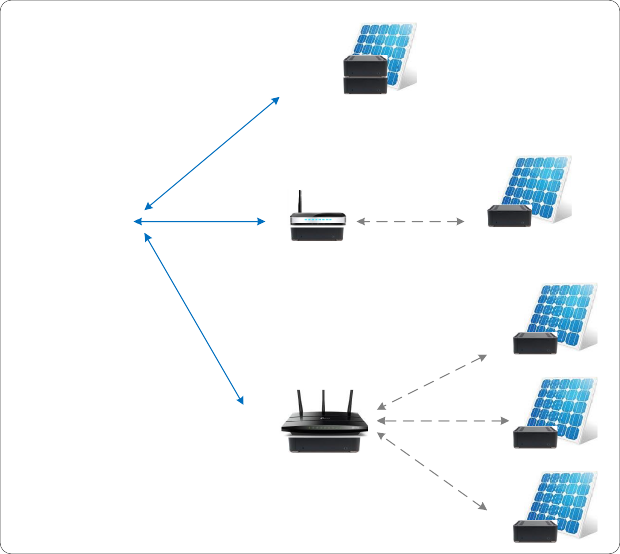
1. Scenario 1: Direct DER Communications – In this scenario, the utility communicates with the DER system directly. This scenario applies when the DER owner wishes to interact directly with the utility for managing their DER or when the utility needs to control the DER for proper system operations. The DER system itself can be architected in many ways. In this guide, the term “DER Client” is used generically to refer to any of the client devices shown in Figure 1.
a. DER with Embedded or Separate Smart Inverter Control Unit (SMCU)1 – In this architecture, a Smart Inverter Control Unit is used to provide the communications component for a single DER and appears as a single IEEE 2030.5 EndDevice to the utility server. The SMCU can be integrated with the DER, or it can reside external to the DER. The communications path between the SMCU and DER is outside the scope of this guide.
b. DER with Generating Facility Energy Management System (GFEMS) – In this architecture, a Generating Facility Energy Management System mediates communications between the utility and one or more local DERs under its control. The GFEMS appears as a single IEEE 2030.5 EndDevice to the utility server and optimizes energy in the context of the overall energy. The communications path between the GFEMS and its DERs is outside the scope of this guide. The likely applicability for this architecture is for future residential, commercial or DER plant operations at a single point of common coupling, each of which will have differing requirements. This model may also be used to represent micro-inverters managed by a central controller.
![]()
1 SMCU and GFEMS are terms used in Rule 21 Regulatory Documents
DER Client 1
DER Client 1
DER Client 1
DER
SMCU
DER
SMCU
DER
SMCU
DER with integrated Smart
Inverter Control Unit (SMCU)
DER with integrated Smart
Inverter Control Unit (SMCU)
DER with integrated Smart
Inverter Control Unit (SMCU)
DER Server
DER Server
DER Server
DER Client 2
DER Client 2
DER Client 2
DER with
external SMCU
DER with
external SMCU
DER with
external SMCU
IEEE 2030.5
IEEE 2030.5
IEEE 2030.5
Out of Scope
Out of Scope
Out of Scope
DER
DER
DER
SMCU
SMCU
SMCU
Not Specified
Not Specified
Not Specified
DER
DER
DER
DER Client 3
DER Client 3
DER Client 3
Out of Scope
Not Specified
Out of Scope
Not Specified
Out of Scope
Not Specified
SMCU
SMCU
SMCU
DER
DER
DER
Generating Facility Energy Management
System (GFEMS) with integrated SMCU
GFEMS controls multiple DERs
Generating Facility Energy Management
System (GFEMS) with integrated SMCU
GFEMS controls multiple DERs
Generating Facility Energy Management
System (GFEMS) with integrated SMCU
GFEMS controls multiple DERs
DER
DER
DER
Utility Commications Gateway
IEEE 2030.5
IEEE 2030.5
IEEE 2030.5
IEEE 2030.5
IEEE 2030.5
Figure 1 - Scenario 1: Direct DER Communications to IEEE 2030.5 DER Clients
Note that the notion of a DER in CSIP is logical concept generally thought of as one or more physical inverters organized and operating as a single system with a common point of aggregation behind a single point of common coupling (PCC) with the utility. This allows the management of a plant/system possessing a single PCC regardless of whether it is composed of a single inverter or many. It is the responsibility of the aggregator system to manage the underlying inverters to meet the requirements of the settings provided by the utility server. The specific interpretation of the DER being a single entity or a related group is established at the time of interconnection with the utility.
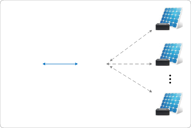
2. Scenario 2: Aggregator Mediated Communications – In this scenario the utility communicates with an Aggregator back end management system rather than directly with individual DERs. The Aggregator is assumed to be managing a fleet of inverters that are distributed across the utility’s service territory rather than having a single point of common coupling. The Aggregator is then responsible for relaying any requirements for DER operational changes or data requests to the
affected systems and returning any required information to the utility. Each DER controlled by the Aggregator appears as an IEEE 2030.5 EndDevice to the utility server. The likely applicability is for fleet operators and aggregation service providers.
DER
SMCU or GFEMS
DER
SMCU or GFEMS
DER
SMCU or GFEMS
DER Server
DER Server
DER Server
Aggregator
DER Client
Aggregator
DER Client
Aggregator
DER Client
IEEE 2030.5
IEEE 2030.5
IEEE 2030.5
Out of Scope
Not Specified
Out of Scope
Not Specified
Out of Scope
Not Specified
DER
SMCU or GFEMS
DER
SMCU or GFEMS
DER
SMCU or GFEMS
DER
SMCU or GFEMS
DER
SMCU or GFEMS
DER
SMCU or GFEMS
Aggregator
Utility Commications Gateway
Figure 2 - Scenario 2: Aggregator Mediated Communications
Each DER SHALL2 connect to the utility in one and only one scenario. The utility will designate the scenario of communications according to the utility’s Interconnection Handbook requirements.